Table of Contents
The EF9369 is a color palette manager. It decodes a 16 color palette to 12-bit RGB (4 bits red, 4 bits gree, 4 bits blue).
Color values
|
|
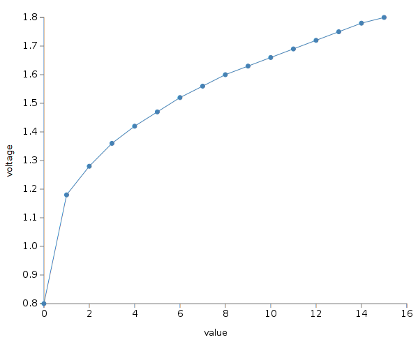
The chip compensates for the expected cathodic ray tube gamma curve. This compensation is quite strong (2.2), and even more so on recent LCD displays, which have a close to linear gamma curve. The result is an image much lighter than expected, except for value 0 which is still very dark. It is important to compensate for this when doing graphics for Thomson machines.
Programming
Registers
E7DA: Data register
Each color is coded on 13 bits (12 color bits and one “mark” bit used to enable video incrustation for the given color).
The first byte written to this register defines the green (high nibble) and red (low nibble) color components. The second one defines the mark bit (bit 4), and the blue level (low nibble).
Writing to this register automatically selects the next byte. So, writing the green/red, then immediately writing the blue byte, will set one color and leave the register ready to accept the next one.
E7DB: Control register
Writing to this register allows to set the address for the next write to E7DA. Each palette entry uses two bytes, so for example setting this to 4 selects the green/red byte for color 2.
Notes
When the CPU accesses the palette IC, the output color will be forced to black. This means it is not possible to change the color palette in the middle of the screen without a visible black artifact (unless the color shown on screen at that time is already black).
